Sunday, September 24, 2017

Fan/Motor System - Part 2 [Belt and Motor]

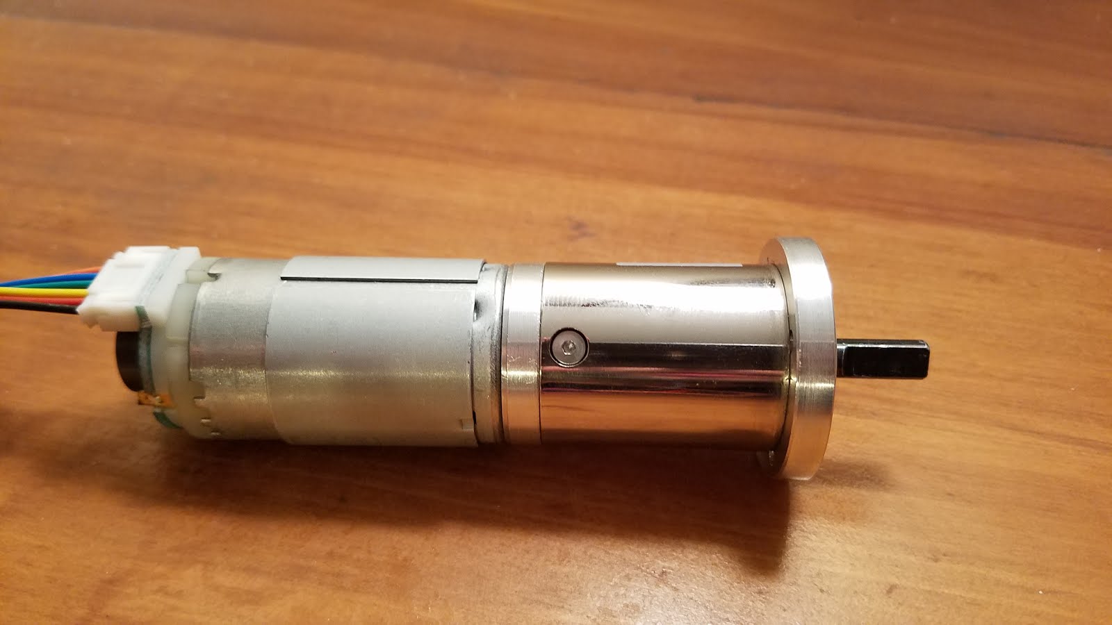
I did a good bit of research on motors and how to choose one that will fit my needs. I ended up buying a 12V DC motor with a gearbox with a max speed of 146 RPM. I also had to find one that could had higher torque ratings than most typical DC motors for hobby projects. The gearbox allows the motor to spin a much lower speeds than with just the motor by itself. The motor I bought also came with an encoder built into it. The encoder is essentially a sensor that reads the speed of the motor. This will come in handy later on. The biggest downside of a DC motor with gearbox is the noise the motor makes. It's a little too loud for what I wanted, but I'm going to be doing some research on how to muffle the sound of the motor.


I built a simple housing unit or mount for the motor. This secures the motor in place with no room to wiggle while it's turning. This unit will be attached to the vibraphone frame. The motor shaft is braced in a plastic rod exactly like the fan rods are held by those plastic rods seen in the previous post. This reduces stress on the shaft and allows the motor run more efficiently because there's less resistance. Not shown in these photos below are 2 pipe clamps wrapped in bicycle inner tube pieces (shown further down). The inner tube pieces acted as filler to eliminate excess space between the top of the motor and the clamps. It's also gives it a very firm grip on the motor, making sure it won't move while running.


Attached to the shaft is the same wheel I used for the rods that spin the fans. I decided on using polyurethane tubing as the belt that pulls the rods. This tubing has the same exact radius as the outer groove on the wheels that will pull it so it should be pretty efficient.


I had to cut the tubing to the approximate length I estimated I would need and then fuse the ends together by melting them with a soldering iron and then firmly holding the ends together. I trimmed off the excess material at the fusing location with an exacto knife. 


I made a pretty simple circuit to control the motor with the Arduino and a potentiometer (It's pretty rough and hideous looking right now). I won't go into how all that works in great detail. But essentially the Arduino uses PWM (Pulse Width Modulation) to vary the speed of the motor. The PWM signal is sent to a MOSFET transistor which then sends the motor a certain voltage for the desired speed. For just controlling the speed of the motor, I don't need an Arduino or any type of micro-controller to do that. But later on I'm going to be using the Arduino to program sequences for the motor to perform hands free. These sequences could be gradually increasing or decreasing speed over a certain amount of time or performing a defined set of speeds and operations based on exact time durations. 


After setting up the Arduino, mounting the motor to the frame, and installing the belt the whole system was ready to be tested for the first time. I made a video to show the whole system and to test out using the audio editing program Audacity to help eliminate the sound of the motor after recording. The motor is simply too loud to record with without any type of editing to the audio. This whole fan and motor system so far has turned out way better than I originally anticipated. To my surprise the fans can spin continuously without scraping on the inside edges of the resonators. I was pretty fearful that would be a problem. 


My next steps are to experiment with eliminating motor noise and also designing a whole electronics control box that will have an easy to use power switch, speed dial, 3 preset buttons, and even an LCD screen to display the RPM and the titles to any preset sequence I might be using at the time. 

Thursday, August 31, 2017

Fan/Motor System - Part 1 [Rod and Fans]

After a year and a half, I finally got around to fully completing the vibraphone... almost. I've started building the fan and motor system, which is what produces that vibrato effect you sometimes hear. When I originally built the vibraphone I decided to not include that feature just because it's really complicated and would add much more time on top of the already lengthy 10 month process. I've had some free time lately so I figured I'd get my hands dirty with this.

When I originally built the resonators I created notches on the tops of them so that I could one day come back and add the rod and fans like I'm doing now. The vibrato effect works by essentially opening and closing the resonators. There is a long metal rod that runs along the center line of the tops of the resonators. At each resonator tube there are metal discs attached to the rod. The entire rod spins via a motor pulling a belt. This creates a constant opening and closing of the tops of the resonators.

I started this portion with the rods. I found a metal supply website that had the exact type and dimension I wanted: 1/4" diameter hollow stainless steel rod. This type is going to be much smoother and straighter than rods you can buy at Lowes or Home Depot. The rod rests inside holes drilled through these plastic rods attach perpendicularly to the resonator frame. These lift the bar up so it doesn't actually touch the resonators anywhere. And fewer points of contact means less friction.


The next step is to make the discs or fans. I used the thinnest aluminum sheet metal I could find at Lowes. I cut them them out into a sort of elongated circle shape a little smaller than the inner diameter of the resonators. 


I didn't cut them into perfect circles because I formed their shape by bending them around the rod so there's a hump in the middle. So after that shape is formed the overall shape looking down on the disc is a perfect circle. 


Then I painted them black... of course. At the high ends of these rods I attached sliding door wheels that will allow the belt to turn the rod.


I used a 2 part 6 minute epoxy to glue the discs and wheels to the rods. The discs were glued alternating direction every resonator to make the whole rod balanced and not weighted more to one direction.


The next thing I need to do is buy a motor and build a housing that it will sit in and attach another wheel to it that will pull the belt. I'm also going to be experimenting with controlling the motor with an Arduino probably. This will allow me to control the fans in ways that you can't do on any other vibraphone, at least that I know of. I made a video to test how the effect of the fans sounds. I simply pulled on a string attached to one of the wheels on the rod under the natural keys. Stay tuned for the next post on the motor. No clue how long that will take though. 


Saturday, December 17, 2016

Cover Song Video Project

I finally got a microphone to record with. I'm an avid listener of Icelandic composer Olafur Arnalds. His music mostly features piano, strings, and sometimes electronics and is often very minimalist. I got a hold of some of his sheet music for free on his website! I discovered that much of his music sounds really fantastic played on vibraphone. The simplicity and tempos of his music makes a perfect transcription to vibraphone. I decided to record every single part to his piece called Near Light on my vibraphone. I also bought a couple of string bass bows on eBay to play the string parts. This is pretty much my first attempt at music recording and video editing. I learned a ton of things about both topics just from getting to try things out on my own. I'm pretty happy with the result. After 10 months of completing the vibraphone and moving it 900 miles, it's still sounding and functioning great. Feel free to leave a comment on the YouTube page.


Wednesday, February 3, 2016

Sound Test Video

I made a simple video to show you how it sounds with and without dampening.


Tuesday, February 2, 2016

The Finished Product

I officially finished building the vibraphone on February 1, 2016. Nine months since I started, or at least since I picked it back up in May 2015. I had no idea what I was getting into when I started. I wish I logged all the hours I put into this, but there's too many to even begin to make a guess. It's a very rewarding feeling to just look back on something you made yourself. By no means is it perfect because there were many mistakes along the way, but I feel very satisfied with it nonetheless. I'll be uploading videos later to show how everything sounds.

After completion, the grand total cost for the vibraphone is $949.10, which includes the cost of tools I had to buy. If you subtract the cost of tools, the cost of materials to build the vibraphone is $647.99. This is pretty amazing because a brand new, manufactured vibraphone (Adams, Yamaha) will cost anywhere from $3,500 - $8,000. If you're interested, I uploaded a spreadsheet showing the cost of each item and all the subtotals.

https://drive.google.com/file/d/0B-4XWjs0sBQiWk4wT0dCS284WFU/view?usp=sharing

I would like to thank Jim McCarthy who runs the website www.makeamarimba.com. There you can purchase very detailed instruction manuals on how to build your own marimba, vibraphone, or glockenspiel. I based my design partly on his plans and partly on my own. But they were a HUGE help to have. I would also like to thank my parents for allowing me to take up half the garage at their house even after I moved out. Also for all the tools my dad had on hand that I didn't have to buy.

Thanks for reading my blog. If you have any questions or comments please leave a comment or email me at conn210@gmail.com

But anyways, here's some pictures. (I have no training in photography whatsoever.)

(click for higher resolution)


Dampener Bar Alterations

To my luck, the changes that needed to be made to the dampener bar were very easy. I knew that the bar was sitting too high against the keys. All I had to do was unscrew the square tubes from the A-frame strut that were jointed to the dampener bar. Then I just screwed them back in a little lower than they were before. This instantly fixed the problem.


I also added 2 more layers of felt to the dampener bar to add more dampening. Zip ties did the trick pretty well. And that's all that needed to be done. The dampener doesn't dampen the keys completely perfectly, but it's good enough for me. It just sounds like the keys are at a half pedal resonance when the pedal is up, which sounds pretty good anyway. Now the whole vibraphone is completely finished! More pictures will be coming in the next post.

Saturday, January 30, 2016

The Dampener

I was hoping for this to be the final step in the construction. After finishing building and assembling the dampener bar, it proved to not work as I intended. More details will come on that later. So I have to go back and figure out some alterations to make to the way the dampener moves in order to get it working properly. So yeah, still not done. But in the meantime here is the post on building the dampener version 1.

Right off the bat I had do a pretty drastic modification to my frame. I had to cut the A-frame completely in half right down the center. This had to be done in order to drill parts into the sides of the struts on the A-frame. If they're connected there physically isn't enough room to fit a drill in there to drill guide holes for screws. It all worked out because the A-frame already had bolt hole locations where it attaches to the lower part of the frame, so the bolt holes still line up, there's just a little slit at each end of the board.


The first item I had to drill into the struts were these 2 little blocks that sit directly over the center of the pedal. These blocks will support the spring mechanism for the dampener and pedal. 


This is the spring I ended up buying on Amazon. 


I got lazy with the pictures for the rest of this. I just took pictures of all the parts after I finished it. The next part is the actual dampener bar, but the structural portion without any padding on yet. It's made from a 3/4" square aluminum tube. The wood blocks at the ends are what connect the ends of the bar to the A-frame to give it support. These are also hinged where they connect with the A-frame to allow the bar to rotate downward. In the middle is the spring mechanism. 


Here's a close up of the spring mechanism and how it's assembled. It works using an eyebolt holding the spring in place with a metal plate. The pedal will be connected to the hook of the eyebolt. The eyebolt is bolted into the square tube. When you push the pedal down, it pulls the whole bar down on the spring and compresses it. The rubber washer is there to eliminate noise from metal hitting against metal. adjusting the wingnut will allow you to raise or lower the resting position (pedal up) of the dampener. 


Here are some pictures of the dampener installed in the frame.


Next I connected the pedal to the spring mechanism with leftover square aluminum tube. It's hinged at the bottom where it connects to the actual pedal. At the top is a hook and eye turnbuckle which will allow you to raise and lower the resting position of the pedal to your preference or if you adjust the height of the whole instrument. 


At the top of the dampener square tube I riveted a long piece of flat aluminum bar. This is what the padding will be attached to. 


For the padding I bought carpet padding and black felt. The carpet padding is glued to the flat aluminum bar with epoxy. I then wrapped the felt completely over the flat bar and carpet padding and glued it to the undersides of the flat bar with epoxy. 


Technically the whole vibraphone should be done at this point, but when I put the keys back on, the weight of the keys caused the bar to sit too far forward and therefore not allow the accidental keys to be dampened enough. Also the whole bar sits too high and doesn't never fully leaves contact with the keys when the pedal is pressed. On the brighter side, with the keys off, the pedal behaves properly and the padding actually dampens the keys properly (at the least the keys it has full contact with). I have to go back and make adjustments to the default position of the dampener bar. Hopefully that isn't too challenging.